Sending measurement values
Inductive IO-Link couplers from Balluff transfer measurement results in the micrometer range reliably and loss-free.
TEXT Dr. Detlef Zienert (Balluff) PHOTOS Balluff
Wherever workpiece carriers are constantly moving and where as in machining centres there is up to 360 degrees of rotation, transferring data from mobile to fixed parts of the system always presents challenges to electronic designers and builders. Inductive coupling systems (BIC) from Balluff are the remedy, transmitting digitized data, signals and even power for the sensors and actuators over a narrow air gap.


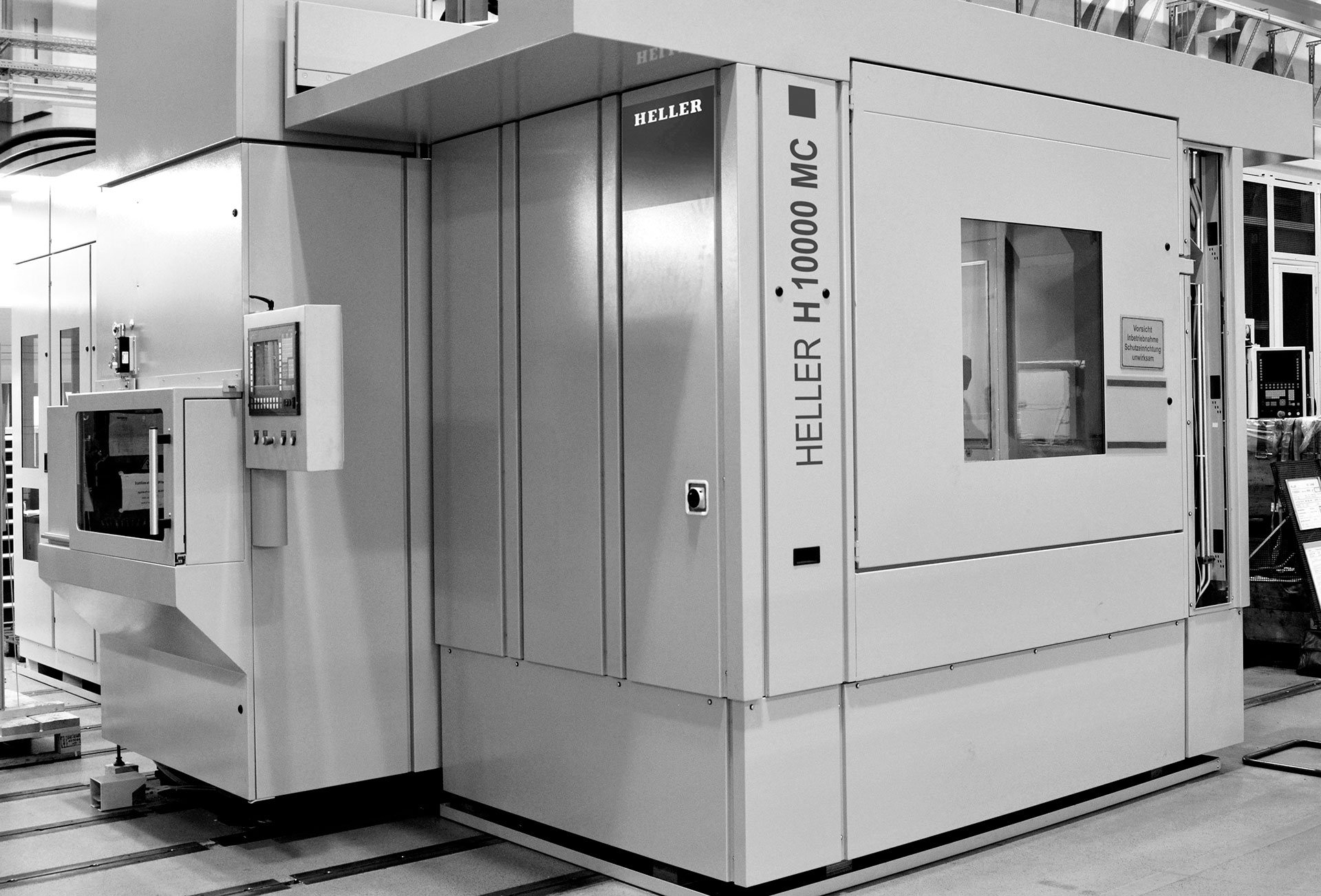
A well-known Scandinavian automobile manufacturer relies on the expertise of HELLER for their truck engine manufacturing. HELLER machining centres run almost fully automatically in a highly modern production line to produce ready to assemble engine blocks from raw castings.
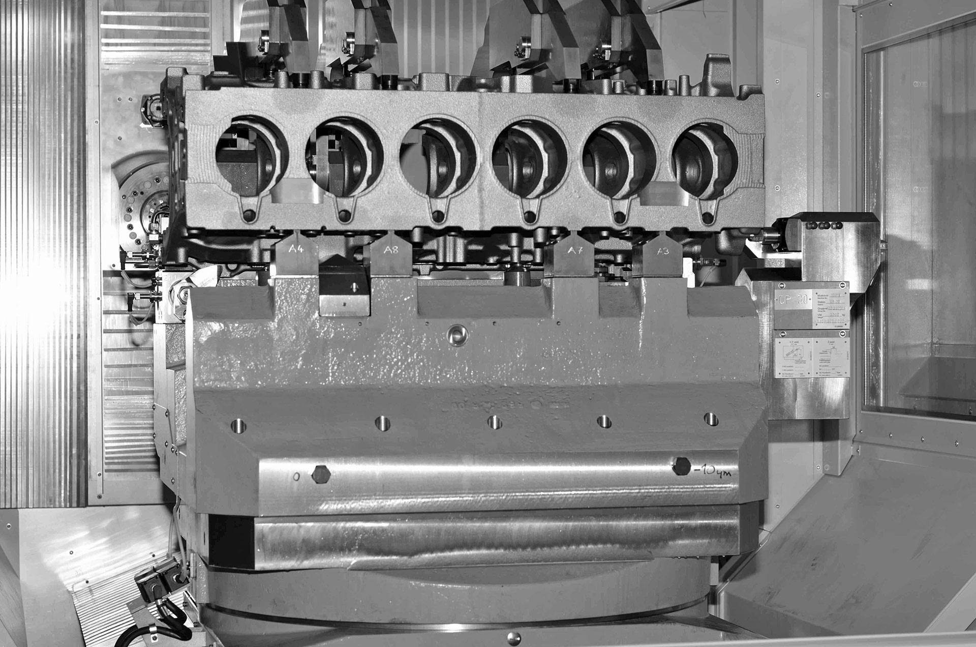
Here is how it works: an automated loading system brings the raw part from above to a 360 degrees rotating index table and secured to the contact area using hydraulic clamping. Since raw block castings usually differ slightly in size due to manufacturing tolerances, as part of the clamping process the relative location of the workpiece on the rotary table is determined and sent to the controller. A bolt located on the base plate detects an index hole drilled in the underside of the engine block, after which four massive swing clamps pull the workpiece back and 16 inductive sensors from Balluff then confirm exact seating. While the casting is moved to its machining position, an inductive sensor registers the distance the bolt has travelled in the indexing hole along with the workpiece. Once the casting is finally in its machining position, the location and dimension data have already been detected and sent to the controller. Machining of the engine block can now begin.
A displacement transducer is used to precisely determine the measurement value as part of the machining and quality control. It compensates for the unavoidable fluctuations in the dimensions of the cast parts to ensure exact and identical machining results.
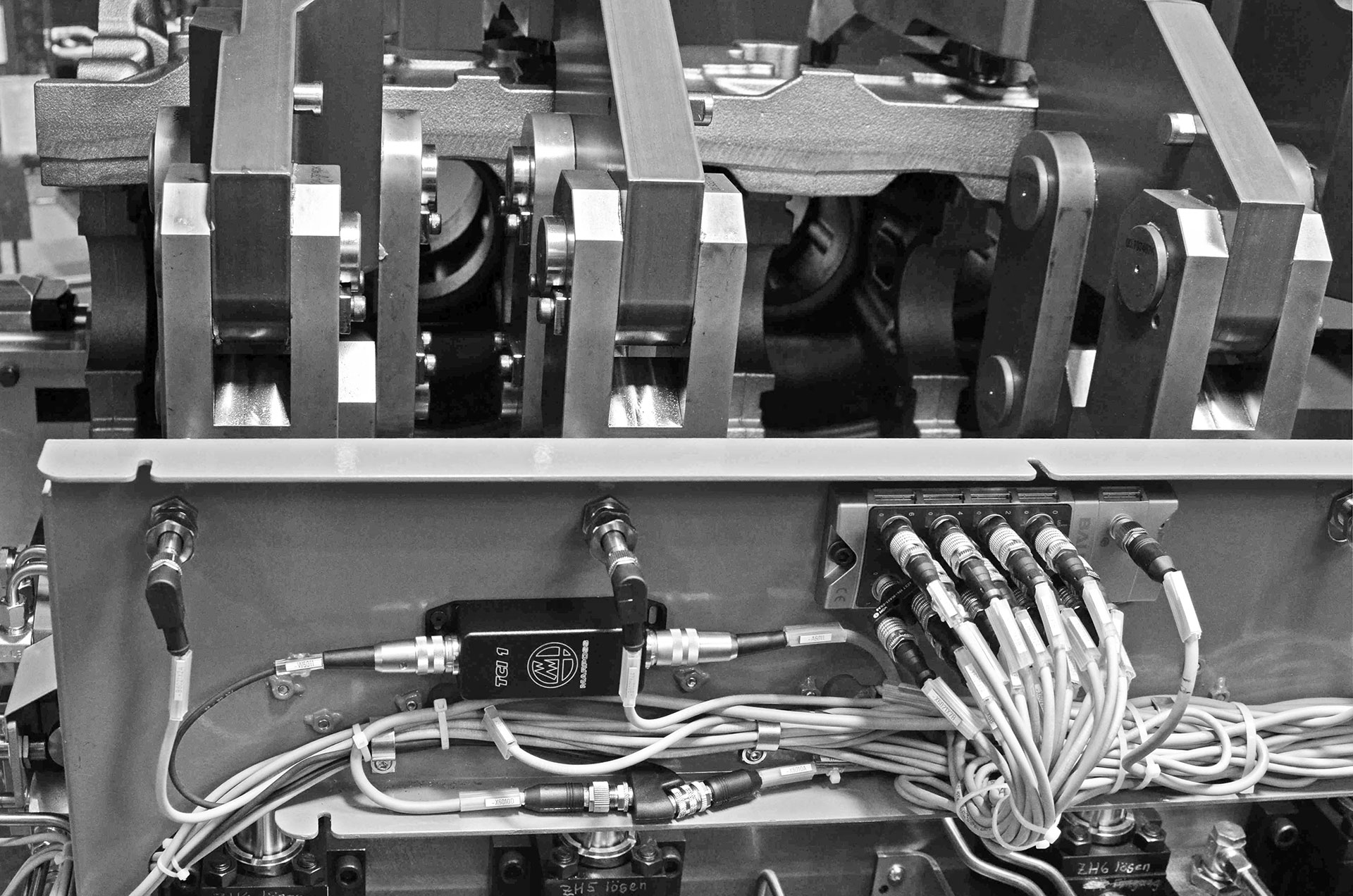
As early as the plant’s design phase the question arises as to how the signals and data should get from the movable and rotatable table to the machine base and thereby to the control level. In line with the contractor’s high productivity and reliability requirements, conventional wiring solutions were out of the question as were slip ring systems: too cumbersome, sensitive, wear-prone and therefore unreliable. HELLER decided on the inductive coupler systems (BIC) from Balluff with IO-Link interface. This transmits signals and power without contact over an air gap of up to 5 mm. The HELLER machining centres have the sender (Remote) and receiver (Base) facing each other and ready for use in the loading and unloading position. In the present case, the system is redundant: one coupler set is responsible for transmitting the length information, the other for transferring the position data to 1/1000 mm accuracy. An analog adapter (A-D converter) takes the analog signal from the Balluff stance transducer and generates an IO-Link signal, which arrives at the Remote sender via standard cable. No shielded cable is required. A sensor hub collects the signals from 16 inductive sensors and the bundled IO-Link signal is transmitted to the second Remote coupler.
The IP 67 non-contacting couplers work reliably and wear-free even in extreme conditions, with transmission unaffected by chips or coolants. With its quick-disconnect units, this intelligent transmission system offers maximum flexibility when it comes to format changes. And in combination with an IO-Link master, virtually any common fieldbus system can be used.

